The forward reverse motor control
is used i a system where forward and backward or upward and downward movement
in the operation are needed.
An example of which are shown in
figures below (a) and (b). Figure below (a) shows forward and backward lateral
movement of an overhead crane driven by motor M. Figure below (b) shows a
downward and upward movement of a load is driven by motor lifter M.
(a) Lateral movement of an overhead crane driven by a motor.
(b) Vertical movement of a lift by a motor.
Control Operation
The
clockwise (forward) and counterclockwise (reverse) rotation of a motor can be
caused by interchanging the connection of any of the two of its three terminals.
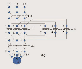
Figures (c) and (d) below will show how this can be done.
Advertisement
Contractors
F and R are interlocked. It means that if the contacts (1-2, 3-4, 5-6) of
contractor R can not be closed. On the other hand if the contacts (1-2, 3-4,
5-6) of contractor R are closed, contacts (1-2, 3-4, 5-6) of contractor F can
not be closed.
Note
that when the contacts of contractor F in Figure (a) are closed, L1 is
connected to T1 through contact F (1-2), L2 is connected to T2 through contact
F(3-4), and L3 is connected to T3 through contact R(5-6).The motor M will run
forward.
When
the contacts of contractor R in the Figure (a) are closed, L1 is connected to
T3 through contact R (1-2), L2 is connected to T2 through contact R(3-4) and L3
is connected to T1 through contact R(5-6). The motor M will run reverse.
Referring
to the control circuit on Figure (a), pressing the forward push button F will
energize contactor F. Maintaining contact F (13 14) will close to maintain
contact or F continually energized even if the forward push button is release.
Contactor F (11-12) will open to prevent contactor R to be energized. Contacts
F(1-2, 3-4, 5-6) will close to run motor M on forward direction.
Pressing
the stop push button will de-energized contactor F. This will cause the
contacts R(1-2, 3-4, 5-6) to open and stops the motor M from running forward.
Contacts F(11-12) will close again. Maintaining contact F(13-14) will open.
Pressing
the reverse push button R will energize contactor R. Maintaining contact
R(13-14) will close to maintain contactor R continually energize evenif the
reverse push R button is release. Contacts R(11-12) will open to prevent
contactor F to be energized. Contacts R (1-2, 3-4, 5-6) will close to run motor
M on reverse direction.
Pressing
the stop push button again will de-energized contactor R. This will cause the
contacts R(1-2, 3-4, 5-6) to open and stops the motor from running reverse.
Contact R(11-12) will close again. Maintaining contact R(13-14) will open. This
brings the condition of the circuit the same as the one shown in Figures (a)
and (b) below.
(a) Control circuit of Forward – Reverse Motor Control with limit switches X and Y.
(c) Connection of Motor to power lines at forward condition.
Read Next Article:---> AUTO TRANSFORMER REDUCE VOLTAGE STARTER
Back to Previous Article:<--- WYE-DELTA REDUCE VOLTAGE STARTER
Video for Installing Led Lights:<--- Installing Mini Driving Light on KTM DUKE 200/390 - Dual Color - Best Cheap Fog/Auxiliary Led Light
Video for Installing Led Lights:<--- Installing Mini Driving Light on KTM DUKE 200/390 - Dual Color - Best Cheap Fog/Auxiliary Led Light


may i know the advantages and the disadvantages for the forward reverse starter?
ReplyDeleteGood Content Sir.. Well Done.. I also use Fluid-Sim to as Simulator.. I used it in installing Led Lights on my Motorcycle
ReplyDelete