Electrical Relay and Magnetic Contactors | Motor Control Operation and Circuits

Electrical Relay and Magnetic Contactors

RELAY AND MAGNETIC CONTACTOR


PEC provisions

The term ―controller‖ includes any switch or devices normally used to start and stop by making or breaking the motor circuit current.

For portable motor rated at 1/3 horse power or less, the controller shall be permitted to be an attachment to plug or receptacles.

Controller designs

  • Each controller shall be capable of starting and stopping the motor it controls
  • Auto transformer shall provide an on and off position, a running position, and at least one starting position. It shall be designed that it cannot rest in the starting position or any position that will render the overload device inoperative
  • The controller shall have a horse power rating not lower than the horse power rating of the motor

NEC provisions

The National Electrical Code (NEC) defines a controller as a device or group of devices that serve to govern, in some predetermined manner, the electrical power delivered to apparatus to which it is connected. As it is applied to control circuits, this means anything from simple pendant switch to complex circuit that may include relays, contactors, timers, switches and indicating light.

Certain example of simple electrical circuit is a bulb and the switch used to control the bulb on and off. In some complex example, the motor control can be used to start and stop a motor controlling a small water pump. In a more difficult task, motor controller can be used for reversing, changing speed, jogging, sequencing or a traffic light control and conveyors.

Electrical control can be operated manually or automatically. For example, some may have a toggle switch and manual starter to start and stop the motor. Some machines are started and stopped automatically, but it is still a common practice that manual and automatic operation are integrated in a control circuit. To fully understand this course, the following contents must be considered.
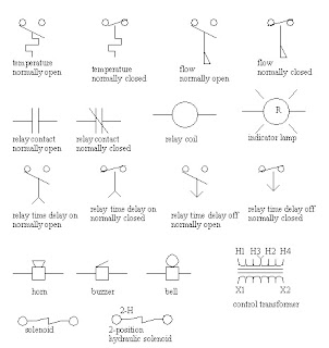
Relay and Magnetic Contactors.jpg


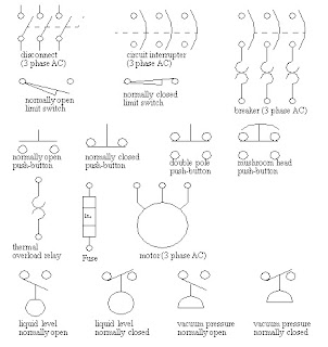
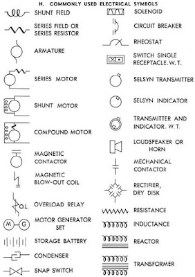
Electrical symbols

In order to understand the basic ideas and information being given, familiarization of the symbols are greatly in need. Symbols are the language of control system.

Relay and Magnetic Contactors Electrical Symbols


Relay and Magnetic Contactors Electrical Symbols


Relay and Magnetic Contactors Electrical Symbols


Electrical materials and equipment used in the control system


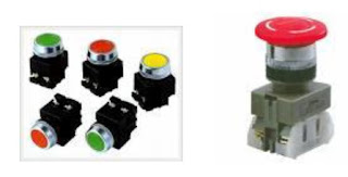
  • Push button switches

These are control devices used to manually open and close the set of electrical contact. It may come in flush mount or extended mount with mushroom head. The contacts may be normally closed, normally open or combination contacts.

Relay and Magnetic Contactors Push Bottons

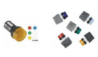
  • Pilot lights

It is a visual information which indicates that circuit is in operation. Lights are usually used for on and off operation, indicating, caution, changing set-up and alarm signaling. The pilot light may come in red which is visual indication that motor is running, green it normally indicates that the system is off or de-energized. Some pilot lights come in blue, white and amber.
Relay and Magnetic Contactors Pilot Lights


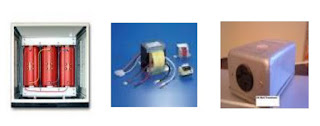
  •  Control Transformer

Control transformers are used to step the voltage needed in the given operation of the circuit. It is often desirable to operate at the control circuit at a low voltage operation.
Relay and Magnetic Contactors Control Transformer


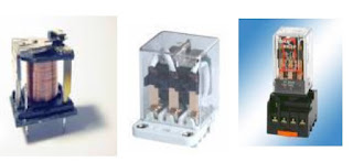
  • Control Relays

The most commonly control components is the relay. They are used widely for switching several contacts of starting coil, pilot light and some audible alarm. This can also be used for switching to separate the high and low voltage source and AC and DC source.
Relay and Magnetic Contactors Control Relays


  • Overload Relay

Overload relays are designed to meet the special protective needs of motor control circuits. Over load relays:
- Allow harmless temporary overload, such as motor starting, without disrupting the circuit.
- Will trip and open the circuit if current is high enough to cause motor damage over a period of time
- Can be reset once the overload is reset

  • Trip class

Overload relay are rated by a trip class, which is defined as the length of time. It will take for relay to trip in an overload condition. Trip classes are class 10, class 20 and class 30.


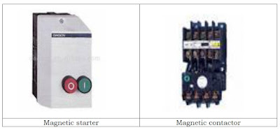
  • Magnetic contactor and starter

The function of the magnetic contactor is similar to electromagnet, its main purpose is to hold contact while the system is in operation. For example, a magnetic contactor is used to control the operation of power pump. The magnetic field of the contactor attracts the armature to the magnet which in turn closes the normally open contacts and opens the normally closed contacts.
When the electromagnetic coil is de-energized, the magnetic field collapse and the movable contact is released under spring pressure.

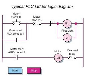
Relay and Magnetic Contactors Ladder Diagrams


Share on Google Plus

About

    Blogger Comment
    Facebook Comment

0 comments:

Post a Comment