Many people can read and understand schematics known as label or line diagrams. This type of diagram is like taking a photograph of the parts and wires all connected up. These diagrams show the actual location of parts, color of wires, and how they are connected. Figure 1 is a typical example of one of these diagrams, taken from a condensing unit of a well-known manufacturer of residential air conditioners.

Figure 1.
Control Operation
Figures 10 (a) and (b) illustrate the power and control circuit respectively of a “Magnetic Primary Resistance Starter”.
The one thing these diagrams don’t do is show how anything actually works! The schematic, or ladder diagram, does this. See Figure 2.

Figure 2.
Note how much cleaner and simpler a ladder diagram is. The layout is designed not for parts location, but to explain how everything works. Some knowledge of electricity is required to “read” or understand a ladder diagram.
Most mechanics prefer label diagrams, so many manufacturers will combine label and ladder diagrams to make wiring diagrams for their equipment. These are “hybrid” diagrams. Hybrid diagrams are very common, and work quite well. Whatever works is best, as long as the customer can understand it. With a little practice, you will be able to make simple diagrams.
Since we will be dealing with simple diagrams, a good rule of thumb is to remember that a typical circuit consists of a power source, a switch, a load, and a ground. Think of electricity as being like water. As water “flows” through a pipe, electricity “flows” through a wire. Electricity flows from a power source, through a switch, through a load, to the ground. Switches look basically the same on diagrams. Special symbols may be used to show the operating force that activates the switch. Ordinarily, there will be only one load in a circuit.
A typical common circuit would look like those illustrated in Figure 3.

Advertisement
Figure 3.
The hybrid is typical of what a simple sketch would probably look like. It could be labeled, if needed. In fact, it is a good idea to label the terminals on the controls if there could be any chance of using wrong terminals on a control. Our example, the hybrid sketch (Figure 3), the thermostat representation would probably be a SPDT stat and have R, W, and Y terminals. Since this is a cooling, make on rise of temperature application as shown by the ladder diagram, you’d want to label the terminals to be used on the thermostat, R and Y.
Switches will look basically the same on simple diagrams. Special symbols can be used to designate the force that makes a switch operate.
Switches are designated by the number of poles and throws. Poles refer to the number of switches operated by a single force. Throws refer to the number of “on” positions. Therefore, a single pole, double throw (SPDT) switch is one switching mechanism with two “on” positions. See Figure 4 for the various ways switches can be drawn.

Figure 4.
There are many “loads”. All can be represented by some kind of resistance or energy consuming symbol. Let’s practice making a hybrid diagram that a typical customer may ask for.
Here’s a simple design specification example. A space needs to be ventilated when the temperature or humidity gets too high. A damper is to open and when it is opened, an exhaust fan will turn on. With the two preceding conditions met, an indicator lamp will light. The system will all be low voltage to save on wiring costs. We now have the information to begin a wiring diagram. (We are not going to pick the devices by number that we need to do this job. Generic nomenclature will suffice, since we are demonstrating the making of a wiring diagram).
The components of the diagram will include a transformer, low voltage source, thermostat (switch), humidistat (switch), low voltage damper actuator (load), low voltage light (load), and a contactor with a low voltage coil (load).
Try and make ladder type diagrams. As you will see, they actually are easiest to make because they follow logical steps and current flow can be traced quickly. A ladder diagram can also be quickly converted to a label diagram, simply by identifying terminals and even color-coding the lines representing wires. Remember, we’re not trying to be purists, but to make an understandable hybrid diagram. Ask yourself these questions before you begin to sketch a diagram:
• How many loads are there to control?
• How many switches are there to control the loads?
• How many loads is a switch going to control?
• How many switches are going to control a load?

Figure 5.
Start with the power source, in this case, a transformer. Standard practice is to construct ladder diagrams to read left to right, so our power source leg is the left line and can be considered as the “hot” (L1) power source. See Figure 5A.
Always keep in mind our current flow path--from power source, through a switch, through the load, to ground. Next, add a switch, a load, and go to ground. Figure 5B and 5C show what this would now look like, with C being more representative of what a basic sketch would look like. (Diagrams are usually made so that switches and loads are shown in their “normal” or de-energized positions.)
If the switch is “closed” or “made”, the load will be energized. Our current flow is from the power source, through the switch, through the load, and to ground. There are no short circuits; that is, a current path to ground with no load. There are no “opens”; that is, a blocking of current flow to ground when the switch is closed. Will this work? Well, partially, but the design also calls for two switches to control the loads. Let’s add the other switch to control the load. If we add this switch in “series” as shown in Figure 5D, both switches would have to be “made” before the load could be energized. This is not in the design specification. Each switch must be able to operate the loads. Therefore, we’ll have to “parallel” the switches as shown in Figure 5E. Checking the circuits, we see we’ll have current flow through either switch to energize the load. We still have more loads to deal with. We need to start a fan and light a light, two more loads. Be careful not to put loads in series! The voltages across the loads will vary if placed in series! By placing the loads in parallel, the same voltage will be present across all the loads. You can add the contactor contacts (shown as a two pole) to the exhaust fan (E.F.) circuit. See Figure 5F.
Figure 5F is a perfectly workable diagram, but let’s clean it up. Labeling the diagram leaves no room for error. To label the diagram, now you will have to know what devices you’re using and how they work. For example, let’s say our thermostat is a T87F, our humidistat a W43A-14, the damper motor an M836, the contactor or relay an R8222D, the light a 32RG18-2111T, and an AT140A1000 transformer.
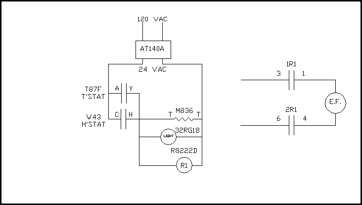
Figure 6.
Figure 6 is the result of labeling the Terminals and wires. On a T87F, R makes to Y on temperature rise. The W43 makes C to H on a rise in humidity. The M836 motor terminals are T and T. R1 is the coil of the R8222D. (The coil wires on an R8222D are not coded. Cast into the plastic of the housing is the word “coil”, and arrows point to the proper terminals). 1R1 and 2R1 are the contacts associated with the coil, R1. When R1 is energized, 1R1 and 2R1 will close, starting the exhaust fan.
Now everything will work as specified. Sometimes, by making a diagram, you can catch errors in logic or a better way to accomplish what the customer wants to do. Such as with this system, you may have noticed an M836 has an end switch that could be used to start the exhaust fan, if the voltage and amp draw of the fan motor can be handled by the end switch. We could eliminate the R8222D if one wants to use the auxiliary switch. Depending on the importance and how critical the annunciation of the “on” light is, it would be best to add an SML fan prover to annunciate the “on” light. The way the light is wired now it only really proves the thermostat or humidistat made a circuit, not that the damper opened or fan actually went on.
Knowing how to read wiring diagrams and being able to make simple diagrams will be of great benefit to you and your customers.
Figure 7.
Figure 7 is an actual diagram made by one of the Milwaukee inside sales people for a customer, to show him how to bring on an indoor blower in both heating and cooling.
0 comments:
Post a Comment